Barn Island Wildlife Management Area - Sentinel Monitoring
Waterfowl Impoundments
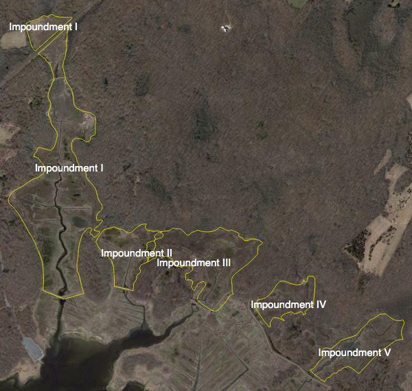
The Connecticut Board of Fish & Wildlife began the construction of four waterfowl impoundments from 1945 to 1947. A fifth impoundment was construction in 1968. The term impoundment is derived from the practice of constructing an earthen berm (dike) or concrete dam to impound water. The impounded areas are the marsh segments that occupy narrow drowned (by seawater as sea levels rose) valleys between the uplands and the dikes are typically constructed where the valley is narrow (see figure 1). [Note: In Miller 1948, impoundment #'s 1 and 2 are reversed reflect date of construction.] The resulting flooding of these marshes was expected to attract waterfowl, shorebirds and wading birds to help offset declining populations of waterfowl in the Atlantic flyway and marsh bird use that followed from mosquito ditching of 1931-1932.
|
| Figure 1. Location of the five impounded tidal wetlands at Barn Island. These wetlands occupy valleys drowned by rising seas. (Source Miller 1948) |
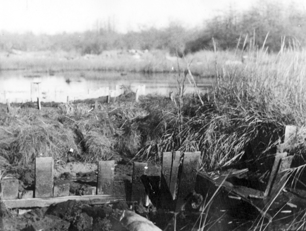
Impoundment 2 was the first valley marsh to be diked and flooded in the fall of 1945. This is the shortest dike measuring 314 feet in length. It was constructed by hand using a double row of vertical planking that was staked in place (see figure 2). The width between the planks was only 10 inches. Plank height above the marsh was 8 to 10 inches. The form was filled with peat excavated from the wetland on the landward side of the dike. In the dike section that crossed the tidal creek, upland soil was used together with the peat. This section was leaky and the borings of fiddler crab into the peat contributed to seepage of water from the impoundment. During extreme high tides in the spring and the fall, portions of the peat in the dike floated away. The pressure of tidal water pushed the bulkheads out of alignment.
|
| Figure 2. Photograph of the vertical planking used for dike construction at impoundment 2. (Source Miller 1948) |
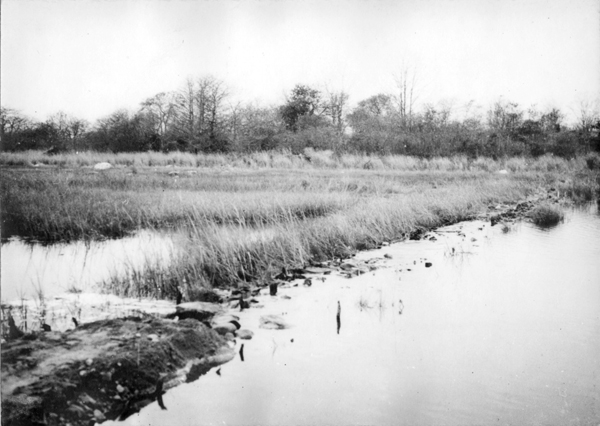
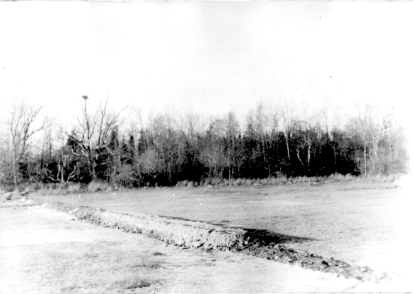
In 1946, the bulkheads were reset to a vertical position, the width of the dike was increased with additional peat secured in place with chicken wire. In the fall of 1947, leaks at the tidal creek were repaired and the surface of the dike was raised 4 to 6 inches with loose loam from the upland (see figure 3). Much of the maintenance was possible due to the assistance of the State Board of Mosquito Control.
|
| Figure 3. New fill (lower left corner of photo) placed at dike 2 in the fall of 1947 to increase the height and width of the dike. Impoundment is on the left and the natural marshes are on the right. (Source Miller 1948) |
Impoundment 1 was constructed in 1946 with heavy machinery provided by the CT State Highway Department and special equipment from private contractors. Fill was excavated from the uplands west of the marsh with a steam shovel and then transported by dump trucks to the marsh. A bulldozer was used to level the fill as the dike was constructed in an easterly direction. A concrete culvert was placed at the location of main tidal creek. It was planned to add a tide gate but this was not implemented and the culvert was filled. The dike was planted with rye grass to prevent erosion by the highest tides, which washed across the dike. This was somewhat successful but in the winter, a severe washout occurred and sandbags were used to close the gap. The dike was used initially for vehicle access to the Headquarters Island but rutting of the dike required a cessation of vehicle access.
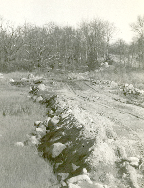
Construction of dike 3 began in the fall of 1946 and was completed in early winter 1947 (see figure 4.). Steam-shovel, bulldozer and dump trucks were used in the construction. There are two sections of dike, one section connects the upland to the west to a small upland island of shrubs – orientation SE to NW. The second section runs from the shrub island in a NE direction and this dike fills the main meandering creek that provided tidal flow to impoundment IV.
|
| Figure 4. Narrow low earthen dike at impoundment 3 (1947). Top photo is the SE-NW dike section and bottom photo is the SW to NE section. (Source Miller 1948) |
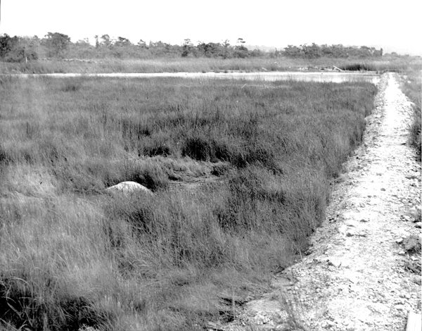
Dike 4 was constructed in the winter of 1947 using manual labor. Gravel was hauled from a barrow pit located near impoundment 3 by wheelbarrow (see figure 5). A leak developed in the dike during late summer and the impoundment drained. Even though the leak was repaired, leakage was still occurring in November.
|
| Figure 5. Image of dike 4, view looking westward. Note the dominance of short-meadow vegetation on the left and right (impoundment) side of the dike. In the background, notice the Osprey nest constructed on the top of a tree. Today most osprey nest on man-made platforms. (Source Miller 1948) |
In 1947, fill (see figure 6) was placed across the Brucker Marsh and there was a small stone bridge at Brucker Creek (location was just south of present day dike). Gross (1966) maps this feature as a dirt road.
|
| Figure 6. Fill placed across the Brucker Marsh in 1947. |
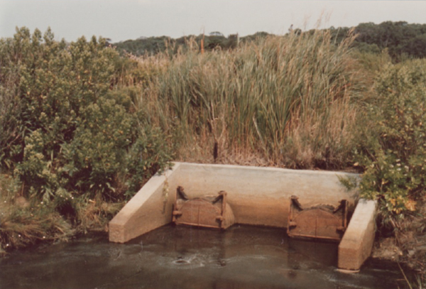
Dike number 5 was constructed in 1968 by extending dike 4 eastward and constructing a channel on the north side of the dike. The channel would allow surplus water to between these two impoundments. The channel construction was also a source of fill for the dike. The dike was equiped with a pair of culverts and water control structures (i.e., tide gates and weir boards; see figure 7).
|
|
| Figure 7. Top figure shows the downstream water control structure installed at Dike 5 in 1968. There is a concrete headwall with opening for two culverts. Tide gates hung on the culverts and as show here are closed. At low tide, freshwater from the impoundment can discharge through the gates and when the tides are high on the bay side, the gates close preventing the inflow of saltwater. The bottom figure shows the upstream structure – on the far side is a concrete headwall containing the two culverts. Vertical concrete walls lie perpendicular to the headwall and a slots in the concrete are for weir boards. The number of boards regulates the height of the water in the impoundment. Photo credit George Hebard (1980). |
Miller (1948) had predicted that impoundment construction would lead to the spread of emergent vegetation especially narrow-leaved cat-tail. The sequence of vegetation from 1946 to 1988 is described in a paper by Barrett and Niering (1993). The associated GIS coverages are found in the data subdirectory of the Data Catalogue of this website.
Below is a list of management activities at the impoundments following the initial construction:
- 1950’s: In the early 1950’s, the dikes were widened and elevated and water control structures were installed in dikes 1, 2 and 3.
- 1965: begis management activities to control common reed.
- 1968: dike 4 is extended across the Brucker Marsh to the east to create impoundment 5 and the two impoundments are connected by a canal to facilitate the exchange of freshwater.
- 1970: A series of east-west channels were constructed to connect impoundments 1, 2 and 3. A sluice gate was added to the culvert on the west side of Headquarters Road to increase water management options.
- 1975: Aluminum squashed (oval in cross-section) culverts with half-round aluminum risers (these hold weir boards) were installed in dike 2 and 3 as a means to further reduce the spread of emergent vegetation by regulating water levels. [These pipes were ordered in November 1974 and thus it should follow that the pipes were installed in 1975.]
- 1976: Impoundment 5 is drained and planted with Japanese millet (Echinochloa frumentaceae), a desirable food plant for duck. By the fall the growth of this grass was vigorous and the marsh was flooded to provide foraging habitat for waterfowl. A portion of the channel connecting Impoundment 2 to 3 is filled so that these could managed independently as was the original design of the 1940’s.
- 1978: A third aluminum culvert with half-round riser is added at dike 1 and salt water is introduced as means to check the spread of cat-tail, the dominant vegetation.
Figure 8 includes a series of photographs showing the condition of the impoundments prior to restoration of tidal flow.
|
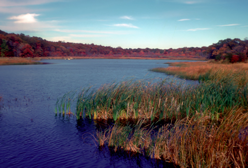
Impoundment 1(1974). The tall emergent vegetation is narrow-leaved cat-tail (Typha angustifolia). Except for the main channel, there is little open water habitat on the marsh for waterfowl. Photo credit Dr. William A. Niering. |
|
Impoundment 2 (1974). The elevation of the weir boards in this impoundment created shallow water habitat to the left and right of the main channel but short marsh vegetation remained on the creek bank levees. Photo credit Dr. William A. Niering.
|
|
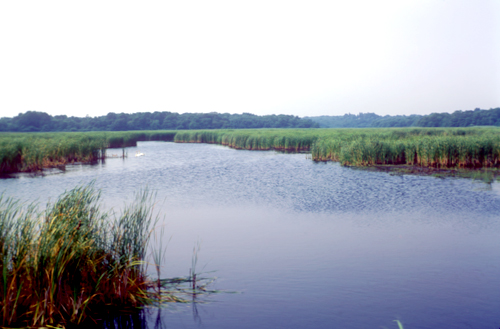
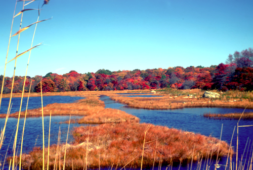
Impoundment 3 (1983). The weir boards were set at elevation to create a shallow pond. The impoundment was flooded by the highest spring tides to make the waters brackish which would be favorable for the growth of widgeon grass (Ruppia maritima). Photo credit Dr. William A. Niering. |
|
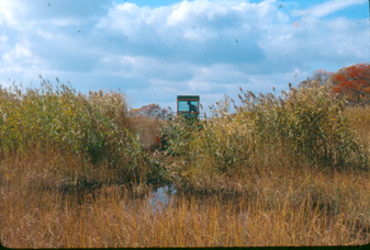
Impoundment 4 (1986). The dominant vegetation was tall Phragmites australis. The Mosquito Control division is using the amphibious rotary ditching machine to remove sediment from the main tidal creek in preparation for tidal flow restoration. Photo credit: Ron Rozsa |
|
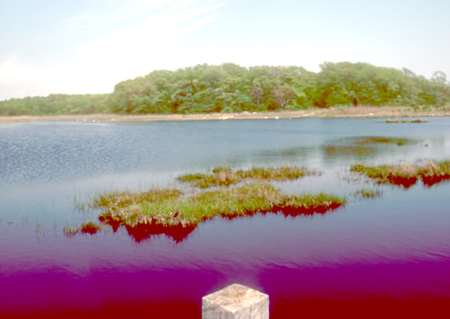
Impoundment 5 (1974). Impoundment 1 was flooded to create a shallow freshwater pond. Photo credit Dr. William A. Niering.
|
| Figure 8. Photos showing the impounded conditions at Barn Island prior to tidal flow restoration activities. |
|